FB Twitter Google Plus
My Basket:

Shopping Cart
Your basket is currently empty.


Click to view the full basket.
Search Site

Call +44 (0)1974 261273

change currency to dollars change currency to pounds sterling change currency to euros
view the basket

Kanda - AVR ISP Circuit Schematics

It is important to layout your PCB correctly to allow trouble free In System Programming of AVR microcontrollers. This guide covers the usual problems that are encountered and typical AVR ISP circuit schematics.


Guide to AVR ISP Circuits

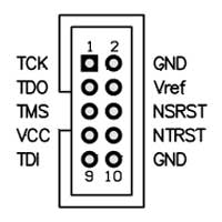
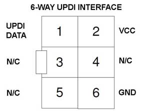
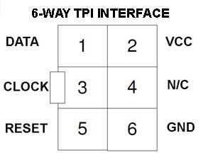
This guide covers Serial Programming, which is commonly called ISP, not JTAG programming which uses a different connector and algorithm. JTAG interface is used for debugging on larger AVR devices (40-pin plus) and can be used for programming as well. Most Kanda AVR programmers also support JTAG. Please see below for AVR JTAG, TPI and UPDI interfaces.

In System Programmers have different amounts of "drive" depending on their price and design, so for maximum flexibility in choosing a programmer, err on the side of caution with sizes unless you have compelling reasons for fitting large capacitors and low value resistors.

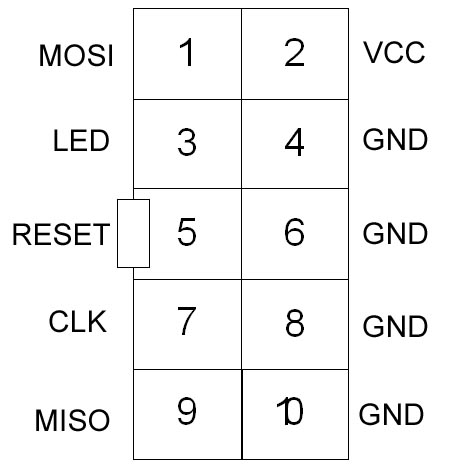
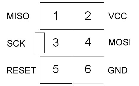
The AVR ISP connector can be either 6 or 10-way, but this makes no difference to your circuit layout. 10-way connectors have more Ground lines to improve noise immunity during programming.

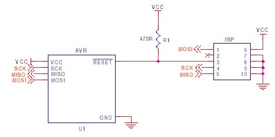
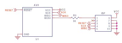
Simple AVR ISP Circuit

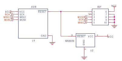
The simplest AVR ISP circuit is shown here, with some notes. Ground and VCC must be connected to programmer, either to power programmer, allow programmer to power target or to provide a reference voltage for lower voltage circuits.

simple AVR ISP circuit schematic


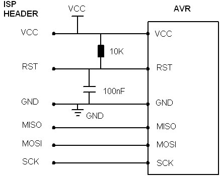
  • Most AVR microcontrollers use MOSI, MISO and SCK SPI pins for programming, but some such as ATmega128 use SPI SCK but use UART TX and RX pins instead for MISO and MOSI. This setup causes more problems than anything else so beware.

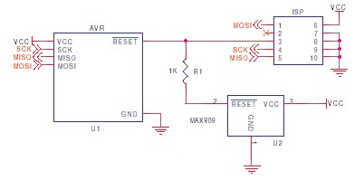
  • The capacitor connected between Reset and Ground, and the resistor from Reset to Vcc should be fitted to give a slight delay to allow AVR to power up properly. These values are not critical, but if they are too large then the ISP programmer will need to be slowed down.

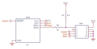
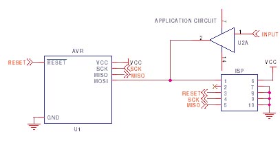
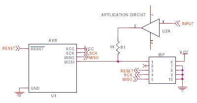
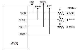
  • The programming lines (SCK, MISO and MOSI) are best left just for programming, but if these pins must be used by the application, then resistors should be used to isolate the application circuitry, typically 4K7. This is especially important if TXD/RXD are used for programming, as UART chips tend to hold the lines.

    avr isp programming lines


    This should be fine for SPI or UART use or where pins are inputs but if you have to use these lines for higher current, then a multiplexer circuit may be needed, see STK200 schematics.

  • Capacitors on the programming lines can cause problems, especially on SCK. If they have to be fitted, then they should be below 10nF and fitted as close as possible to AVR microcontroller pins. Some low cost programmers will have problems with even a 10nF capacitor on SCK or MOSI, so smaller is better.

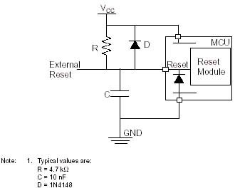
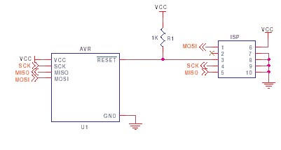
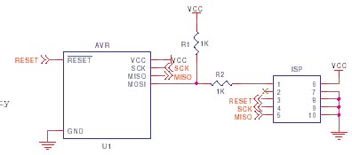
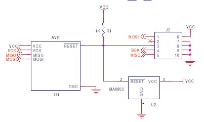
Atmel AVR ISP Reset Circuit

Atmel recommend that a diode is fitted between Reset and Vcc as shown here, but we have not found it necessary in practice. Note their recommended resistor and capacitor values are slightly different, but these values are not critical. A capacitor between 10nF and 100nF and a resistor between 4K7 and 10K will be fine.
Atmel AVR ISP Circuit Schematic


Standard ISP Header Layouts

Most engineers use either a 10-way ISP Header or a 6-way ISP header on their PCB. Both formats are 0.1" (2.54mm) dual-in-line pin headers with a keyway for orientation. 1.27mm (0.05") and 2.0mm pitch are sometimes used to save PCB space. Most programmers use 10-way header but Atmel have swapped to 6-way. Adapters are available to swap from 10-way programmer leads to 6-way headers.

JTAG interface is also 0.1" (2.54mm) pin header. JTAGEN fuse must be set for JTAG interface to work. The JTAG lines can be used for other JTAG devices without problems but if JTAG pins are used as general I/O, then they should be fitted with isolating resistors just like ISP lines. Kanda programmers use an adapter to swap to standard Atmel JTAG interface shown - target layout view.

Kanda supply adapters to convert to 2.0mm and 1.27mm (0.05 inch) 10-way headers for both ISP and JTAG. Micromatch and flying lead adapters are also available and Kanda can make any custom adapter you might need, please contact support.

AVR Programmer Adapters

10-way target layout

Atmel AVR ISP Circuit Schematic 10way header

6-way target layout

Atmel AVR ISP Circuit Schematic 6way header

10-way JTAG layout

Atmel AVR JTAG Circuit Schematic 10way header

10-way JTAG layout

Atmel AVR JTAG Circuit Schematic 10way header

6-way UPDI layout

Atmel AVR UPDI Circuit Schematic 6way header

6-way TPI layout

Atmel AVR TPI Circuit Schematic 6way header


Example Good and Bad Circuits

AVR ISP circuit schematic 1
The pull-up resistor R1 is too strong, minimum value 1K
OK? NO
AVR ISP circuit schematic 2
The pull-up resistor R1 is at least 1K
OK? YES
AVR ISP circuit schematic 3
A resistor, R1, in series will not affect ISP Programming
OK? YES
AVR ISP circuit schematic 4
The series resistor R2 is ok with pull-up R1 on ISP side
OK? YES
AVR ISP circuit schematic 5
The series resistor R2 with pull-up resistor R1 on AVR side will affect ISP operation
OK? NO
AVR ISP circuit schematic 6
The application circuit is using a programming pin to read the output of U2. This will hold the state of the line, preventing programming.
OK? NO
AVR ISP circuit schematic 7
The application circuit is still using pin as an input to read output of U2, but decoupling resistor R1 allows ISP to control the programming line.

Some programmers will need more than 1K shown, 2K2 or 4K7 will allow all programmers to work.
OK? YES

Example good and bad AVRISP circuits using Reset IC


These diagrams show some common ISP circuits using Reset ICs.

AVR ISP circuit schematic 8
The commomly used MAX809 Brown-out IC has a Push-Pull output. This will hold RESET line high.
OK? NO
AVR ISP circuit schematic 9
This time resistor R1 prevents MAX809 holding Reset
OK? YES
AVR ISP circuit schematic 10
The MAX803 can be used without a decoupling resistor because it has OPEN DRAIN output
OK? YES

AVR ISP Programmers


      Product News       Special Offers       Sena Products       A-Z Product Index       Manufacturer Index       Software Downloads       Contact