


MPLAB X
Create a C project in MPLAB X and make sure the PIC microcontroller is the one you want to use. This code is written for PIC16F1789. If you choose a different device, XC8 will complain about Configuration Bytes unless you change the configuration section.
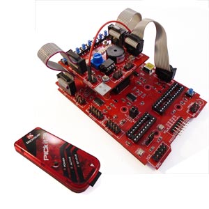
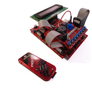
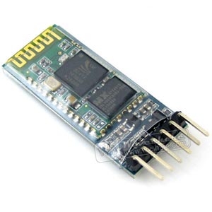
Connect to PC via standard serial cable, not Nul-modem cable or use Bluetooth serial module. Run Hyper Teminal (Programs > Accessories > Communications)or your favourite console program eg Tera Term and create New connection, with Connect Using set to your COM port or Bluetooth Serial Port. In COM Port Properties, set Baud Rate to 9600, Data bits to 8, no Parity, 1 stop bit and no flow control.
This code seta up serial port and waits for a character to be received from PC. It writes this to LEDS on PORT B (RB) and returns it to the PC.
#define _XTAL_FREQ 8000000  // 8 MHz

/*Very Important - change _XTAL_FREQ to match target clock

  This program initialised UART and port for LEDs and waits for a character to be received on the serial port.
	It displays character on LEDS (active low) and then returns it on serial port.
*/

#include <xc.h>
#include "16f1789_config.h" //configuration bits

// Function Prototypes
char UART_Init(const long int baudrate);
char UART_Data_Ready();
char UART_Read();
void UART_Write(char data);

led_display(unsigned char value);

// Main Function
void main()
{
    unsigned char value;

   TRISD = 0x00;  // PORTD as outputs for LEDS
   UART_Init(9600);
  led_display(0b01010101);  // display a value so something is happening

   do
   {
       while(!(UART_Data_Ready()));  // wait for receive character
       value = UART_Read();          // read value sent
       led_display(value);           // display on LEDs
       __delay_ms(100);
       UART_Write(value);            // write it back
   }while(1);
}

 // functions

led_display(unsigned char value){

    PORTD = ~value;
}

char UART_Init(const long int baudrate){
	unsigned int x;
	x = (_XTAL_FREQ - baudrate*16)/(baudrate*16);
	BRGH = 1;
	SPBRG = x;
	  SYNC = 0;
	  SPEN = 1;
          TRISC7 = 1;
          TRISC6 = 1;
          CREN = 1;
          TXEN = 1;
	  return 1;
}


char UART_Data_Ready(){
   return RCIF;
}

char UART_Read(){

  while(!RCIF);
  return RCREG;
}

void UART_Write(char data){
  while(!TRMT);
  TXREG = data;
}
The configuration bytes are in a separate header file, 16f1789_config.h, shown here. If you want to change device, change these.
   // CONFIG1
#pragma config FOSC = ECH       // Oscillator Selection (ECH, External Clock, High Power Mode (4-32 MHz): device clock supplied to CLKIN pin)
#pragma config WDTE = OFF       // Watchdog Timer Enable (WDT disabled)
#pragma config PWRTE = OFF      // Power-up Timer Enable (PWRT disabled)
#pragma config MCLRE = ON       // MCLR Pin Function Select (MCLR/VPP pin function is MCLR)
#pragma config CP = OFF         // Flash Program Memory Code Protection (Program memory code protection is disabled)
#pragma config CPD = OFF        // Data Memory Code Protection (Data memory code protection is disabled)
#pragma config BOREN = ON       // Brown-out Reset Enable (Brown-out Reset enabled)
#pragma config CLKOUTEN = OFF  // Clock Out Enable (CLKOUT function is disabled. I/O or oscillator function on the CLKOUT pin)
#pragma config IESO = ON        // Internal/External Switchover (Internal/External Switchover mode is enabled)
#pragma config FCMEN = ON       // Fail-Safe Clock Monitor Enable (Fail-Safe Clock Monitor is enabled)

// CONFIG2
#pragma config WRT = OFF        // Flash Memory Self-Write Protection (Write protection off)
#pragma config VCAPEN = OFF     // Voltage Regulator Capacitor Enable bit (Vcap functionality is disabled on RA6.)
#pragma config PLLEN = OFF      // PLL Enable (4x PLL disabled)
#pragma config STVREN = ON      // Stack Overflow/Underflow Reset Enable (Stack Overflow or Underflow will cause a Reset)
#pragma config BORV = LO        // Brown-out Reset Voltage Selection (Brown-out Reset Voltage (Vbor), low trip point selected.)
#pragma config LPBOR = OFF      // Low Power Brown-Out Reset Enable Bit (Low power brown-out is disabled)
#pragma config LVP = ON         // Low-Voltage Programming Enable (Low-voltage programming enabled)
If you found this information useful, please give us a mention or share it on Social media.
