
Search Site


7-Segment Display
This page gives instructions on using Kanda 7-segment display modules with STK200 and STK300 kits. The module plugs in to any Port header on the board.7-Segment Display
This table gives the hexadecimal encodings for showing the digits 0 to F on 7-segment display using Kanda 10-way connector. 0 is segment On
| Digit | gbdf(dp)eac | g | b | d | f | dp | e | a | c |
|---|---|---|---|---|---|---|---|---|---|
| 0 | 0x88 | 1 | 0 | 0 | 0 | 1 | 0 | 0 | 0 |
| 1 | 0xBE | 1 | 0 | 1 | 1 | 1 | 1 | 1 | 0 |
| 2 | 0x19 | 0 | 0 | 0 | 1 | 1 | 0 | 0 | 1 |
| 3 | 0x1C | 0 | 0 | 0 | 1 | 1 | 1 | 0 | 0 |
| 4 | 0x2E | 0 | 0 | 1 | 0 | 1 | 1 | 1 | 0 |
| 5 | 0x4C | 0 | 1 | 0 | 0 | 1 | 1 | 0 | 0 |
| 6 | 0x48 | 0 | 1 | 0 | 0 | 1 | 0 | 0 | 0 |
| 7 | 0xBC | 1 | 0 | 1 | 1 | 1 | 1 | 0 | 0 |
| 8 | 0x08 | 0 | 0 | 0 | 0 | 1 | 0 | 0 | 0 |
| 9 | 0x0C | 0 | 0 | 0 | 0 | 1 | 1 | 0 | 0 |
| A | 0x28 | 0 | 0 | 1 | 0 | 1 | 0 | 0 | 0 |
| b | 0x4A | 0 | 1 | 0 | 0 | 1 | 0 | 1 | 0 |
| C | 0xC9 | 1 | 1 | 0 | 0 | 1 | 0 | 0 | 1 |
| d | 0x1A | 0 | 0 | 0 | 1 | 1 | 0 | 1 | 0 |
| E | 0x49 | 0 | 1 | 0 | 0 | 1 | 0 | 0 | 1 |
| F | 0x69 | 0 | 1 | 1 | 0 | 1 | 0 | 0 | 1 |
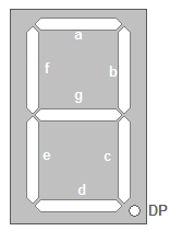
Display Segments
C Code Example
This code is written for WinAVR running in Atmel Studio. Please check that the device selected in Project > Configuration Options matches your target device or the code will not run.The code justs counts Hexidecimal from 0-F and repeats. It has a 1 second delay between characters, on a 1MHz clock. Alter F_CPU constant to match your target clock speed, 8MHz on an STK200 board.
To change the count to Decimal (0-9), change value of dec-hex variable.
To change Port, alter PORT_7_SEGMENT and DDR_7_SEGMENT constants.
/* WinAVR Code to display 0-9 or 0-F to 7-segment display.
Change Variable dec_hex in Main function to swap between
hex and decimal. Warning: clock speed is defined as 1MHz (F_CPU) because new
AVR devices have default 1MHz Internal RC. Change F_CPU to match your clock speed.

There are 7-segments + decimal point (DP) and they are active low, that is 0 = segment on.
DP is always off (1).
PIN wiring is

Pin Segment
7    g
6    b
5    d
4    f
3    DP
2    e
1    a
0    c  */

// clock speed for delay
#define F_CPU 1000000UL  // New AVR devices are at 1MHz Internal clock
                       // STK200 board has 8MHz cystal
#include <avr/io.h>
#include <util/delay.h>

//Configurations

//**************
// Change constant here to change port used by 7-segment

#define PORT_7_SEGMENT PORTB
#define DDR_7_SEGMENT DDRB

void SevenSegment(uint8_t count,uint8_t dp, uint8_t dec_hex)
{
/* This function shows value of count on display the decimal point is displayed if dp=1
Note:
count must be less than 10 for decimal, or less than 16 for Hex. */
   if(count <dec_hex)
   {
      switch (count)
      {
         case 0:
         PORT_7_SEGMENT=0b10001000;
         break;

         case 1:
         PORT_7_SEGMENT=0b10111110;
         break;

         case 2:
         PORT_7_SEGMENT=0b00011001;
         break;

         case 3:
         PORT_7_SEGMENT=0b00011100;
         break;

         case 4:
         PORT_7_SEGMENT=0b00101110;
         break;

         case 5:
         PORT_7_SEGMENT=0b01001100;
         break;

         case 6:
         PORT_7_SEGMENT=0b01001000;
         break;

         case 7:
         PORT_7_SEGMENT=0b10111100;
         break;

         case 8:
         PORT_7_SEGMENT=0b00001000;
         break;

         case 9:
         PORT_7_SEGMENT=0b00001100;
         break;
		 //hex only
		 case 10:
         PORT_7_SEGMENT=0b00101000;  //A
         break;
		 case 11:
         PORT_7_SEGMENT=0b01001010;  //b
         break;
		 case 12:
         PORT_7_SEGMENT=0b11001001;  //C
         break;
		 case 13:
         PORT_7_SEGMENT=0b00011010;  //d
         break;
		 case 14:
         PORT_7_SEGMENT=0b01001001;  //E
         break;
		 case 15:
         PORT_7_SEGMENT=0b01101001;  //F
         break;
      }
      if(dp)
      {
         //if decimal point should be displayed make DP bit Low
         PORT_7_SEGMENT&=0b11110111;
      }
   }
   else
   {
      //This symbol on display shows that count was greater than 9 or 15
      //so display can't handle it

      PORT_7_SEGMENT=0b11011111;
   }
}


int main()
{
   //Setup
   DDR_7_SEGMENT=0xFF;    //All output
   PORT_7_SEGMENT=0xFF;   //All segments off

   uint8_t count=0;
   uint8_t dec_hex=16; //change to 10 for decimal

   while(1)  //loop forever
   {
      SevenSegment(count,0, dec_hex);

      count++;
      if(count==dec_hex)
      {
         count=0;
      }
      _delay_ms(1000);
   }
}
Assembler Code Example
 /*
7-segment display on PORTB increments when button 0 is pressed (PortD)
There are 7-segments + decimal point (DP) and they are active low,
that is 0 = segment on. DP is always off (1).
Change include file for other devices.
PIN wiring is

Pin Segment
7    g
6    b
5    d
4    f
3    DP
2    e
1    a
0    c
 */

 .include "m16def.inc" // change for other devices

   .def temp    = r16
   .def counter = r17
   .def coarse    = r18  // delay routine for switch debounce
   .def middle  = r19
   .def fine     = r20

   // change to change ports
   .equ SEG7_PORT= PORTB
   .equ SEG7_DDR = DDRB
   .equ BUTTON_PORT= PORTD   // Port write register
   .equ BUTTON_DDR = DDRD    // Port direction register
   .equ BUTTON_INPUT = PIND  // Port read register

   .cseg
   .org 0
   rjmp Reset

        // store values to drive 7-segment display
segments: //digits 0-9
   .db 0b10001000, 0b10111110, 0b00011001, 0b00011100
   .db 0b00101110, 0b01001100, 0b01001000, 0b10111100
   .db 0b00001000, 0b00001100
    //hex only A-F
   .db	0b00101000, 0b01001010, 0b11001001, 0b00011010
   .db  0b01001001, 0b01101001

Reset:
   LDI	temp,LOW(RAMEND) ; Set up stack - needed for sub-routines
	OUT	SPL,temp
	LDI	temp,HIGH(RAMEND)
	OUT	SPH,temp

   ser temp             ; 7-SEG Port as outputs (FFh)
   out SEG7_DDR, temp

   ldi temp, 0b11111110 ; BUTTON.0 as input, 0=input
   out BUTTON_DDR, temp

Reset_counter:
   clr counter          ; Initialize to 0
  // load pointer registers with address of segments
   ldi Zl,low(segments * 2) ; * to convert cseg address to byte addressing
   ldi Zh,high(segments * 2)

Start:
   lpm  temp,Z+      ;read a byte from 'segments' and increment Z
   out SEG7_PORT, temp // output to 7-segment display

loop_while_button_held:
   sbic BUTTON_INPUT,0   // button pressed = 0, so skip
   rjmp loop_while_button_held // jump if pin is low
   rcall delay  // switch debounce
   inc counter
   cpi counter, 16 //change to 10 for decimal
   brne Start      // return to start if count not reached

   rjmp Reset_counter


 /// delay subroutine for switch debounce.
 // change value of coarse to change switch response rate
 // For example, $0F for 8MHz
delay:		ldi	coarse,$02
delay1:		ldi	middle,$FF
delay2:		ldi	fine,$FF
delay3:		dec	fine
			brne	delay3
			dec	middle
			brne	delay2
			dec	coarse
			brne	delay1
			ret
Module Schematic
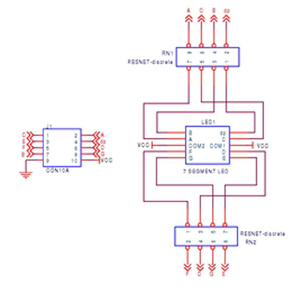
7-Segment Module