
PIC microcontrollers, like most modern microcontrollers, can be programmed in system (or in circuit – ICSP) rather than in a socket programmer. This has advantages in development and in production, for example, to use different firmware for different versions or to speed up production. The major benefit though is field upgrades. We can give you lots of horror stories about people who didn’t think of firmware upgrades and had to recall products to fix a bug, not a cheap option. So how do you add In System Programming to your designs?
The major factors are the electronic design of the ICSP circuit and the ICSP connector format. Let’s look at the connector format first. Most Microchip development boards (and ICD2/3 debuggers) use RJ11 connector by default, but this is a poor choice for field or production use.
For a start, RJ11 is not a recognised standard, and is often called RJ12 instead! Trying to find RJ11 connectors on Farnell or Digikey is really difficult. All it defines is a connector format, like the familiar RJ45 network connector. There are two parameters that define the connector – the number of connectors or poles and the number that are actually connected. The RJ45 is actually pretty standard and it is always an 8 pole connector with all 8 connected, so it is called an 8P 8C connector.
When we get to RJ11 or RJ12 everybody seems to have their own idea, and they can be 4 way like the common telephone jack or 6 way. They may have all the poles connected or not. So we get 4P 4C (telephone) or 6P 4C or 6P 6C. The one we need is a 6P 6C connector, which is what you need to search for with your suppliers.
Even if we eventually find the right connector, they have a large footprint, are not especially cheap and many production and field programmers do not use this format anyway. Kanda programmers do have an optional RJ11 connector if you must use this format but we don’t recommend it. So, what do we do instead?
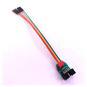
Most PIC programmers come with 6-way flying leads, that are connected to a 6 x 1 standard 0.1″ (2.54mm) pin header. This is much cheaper, smaller and easier to use. The flying leads from the programmer can be connected together in the right order or replaced with a 6 x 1 shroud when the pin order has been defined.
Microchip ICD2 type emulators have a connector available that converts the RJ11 type interface into 6 x 1 pin header format and your best bet is to use this and design your PCB with this connection from the start.
Ok, that’s the connector dealt with, now for the circuit. PIC microcontrollers have two main programming methods, Low Voltage (LVP) and High Voltage (HVP) programming. With HVP, a 12V level on MCLR pin is used to put the PIC microcontroller into programming mode, whereas LVP uses a separate pin with 5V to indicate programming mode.
Newer PIC microcontrollers eg some PIC16F1xxx devices have LVP available on MCLR pin by using a software key to enter ICSP mode. These devices do not have a separate LVP pin so only need 5 pins for low voltage programming. You will need to check the device datasheet to find out if your chip has this feature. If in doubt, you can always use HVP, which is only 9V instead of 12V.
Most people use HVP, and as long as you don’t connect MCLR to other parts of the circuit, you do not need to worry about this 12V signal. Even if you do, a diode can be used as protection. If you use HVP, all PIC programmers provide the necessary 12V voltage so you just need to connect MCLR to ICSP header.
HVP has two methods of entering programming mode, VDD (VCC) first or VPP (12V) first depending on the PIC microcontroller. All Kanda programmers use VPP first if device has this method as it prevents target code from running, especially important if MCLR pin is redefined for other uses, and target isn’t powered. So, the programmer must power the circuit. If you have a circuit that draws lots of current, over 150 mA, then it is a good idea to isolate this circuitry from PIC microcontroller with a blocking diode to reduce current draw from programmer.
Kanda have one customer with a 2F capacitor (yes, 2 Farad!) on their circuit that wasn’t isolated. We had to provide custom firmware to ramp up the voltage, which took over 90 seconds, before programming proper could start.
Apart from MCLR pin, the other pins on the PIC that need connecting to ICSP header are
- PGD – Programming data pin
- PGC – Programming clock pin
- VDD – circuit voltage
- VSS – circuit Ground
- PGM – LVP pin, for LVP method only
Try and keep capacitance on programming pins to a minimum as this can effect the programmer. If programming pins (PGC, PGD) are used for other purposes in your circuit, they should have blocking resistors to reduce load on programmer.
A full PIC ICSP Circuit Guide is available in a new window.
Kanda supply a range of PIC ICSP programmers, especially our range of portable and handheld PIC programmers for field and production use. These make field updates really simple even for unskilled operators. They are also useful on production line as you don’t need a PC or, in most cases, a power supply
PIC Handheld Programmer Category on our shop.
One thought on “PIC In-system Programming”