
When AVR microcontrollers were first introduced in 1995, In System Programming was simple, with one programming method (Serial Programming Interface or SPI) and a recommended 5 x 2 10-pin target interface. For 10-15 years, this stayed the same except for the addition of JTAG programming on some devices and a move towards a 3 x 2 6-pin target header. In the last few years, new interfaces have sprouted like weeds, including TPI, PDI and UPDI. What do this all mean and how does it affect you?
Classic ISP or SPI
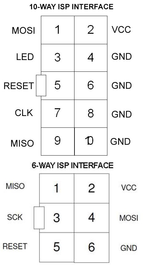
This programming method is simple and gives few problems if you follow the rules on the ISP interface in your circuit – see AVR ISP Circuit Guide. The standard header recommended by Atmel was a 5 x 2 10-Way box header at 2.54mm (0.1″) pitch. This had interleaved ground lines to improve reliability but Atmel decided these weren’t necessary so moved to a 3 x 2 6-way header.
SPI is simple, supported by all programmers and it is hard to lock yourself out of the AVR chip, except some small 8-pin chips that could have Reset pin reconfigured. These then need 12V to clear this Reset pin change and very few programmers now support this.
The downsides of SPI include
- Pin usage – 4 pins needed
- Programming speed tied to target clock, maximum 1/4 of clock frequency
- Slower at low voltage
JTAG Programming
JTAG was introduced on to AVR microcontrollers with 40-pins or more and this bus can also be used for programming. This method is faster and is independent of target clock speed. The downsides are
- Disabling JTAG Enable fuse (JTAGEN) prevents JTAG programming – you need ISP to clear this
- 4 port pins are dedicated to JTAG
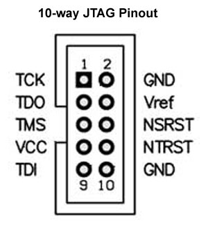
- Target connector is 10 or 14-pin with different layout from ISP
JTAG is available on some ATxmega devices as well as larger AVRs.
TPI Programming
This was introduced for a limited number of ATtiny chips and stands for Tiny Programming Interface. These devices are ATtiny10, ATtiny102, ATtiny104, ATtiny20, ATtiny4, ATtiny40, ATtiny5 and ATtiny9.
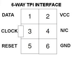
It is a 2-wire interface that uses Reset pin for clock and a dedicated pin for data. From a users viewpoint, it is exactly the same as ATxmega PDI interface. It is the only interface available on these particular ATtiny devices so has to be used for them.
These ATtiny devices are very small and cheap but are not available in DIP package and are not widely used.
PDI Interface
This is the programming interface available on all ATxmega microcontrollers, although some also have JTAG as well. It is functionally the same as ATtiny TPI interface and uses the same two pins – RESET for clock and a dedicated pin for programming data.
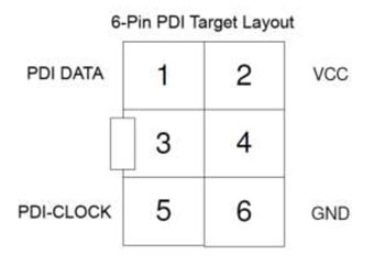
There are strict rules about Reset circuitry to prevent any programming issues. Any pull-up resistor should be a minimum of 10K or removed altogether, any reset decoupling capacitor should be removed as should any other load on RESET. PDI data pin should be dedicated to programming only. A 3 x 2 6-pin target header is suggested by Microchip.
It is a fast programming method using Synchronous Serial Port (UART data with a clock or USART) and typically copes with 230,400 Baud but this will need to be slower at lower voltages.
UPDI Interface
This is the latest programming method and since Microchip took over Atmel, it seems to be the preferred method for all new AVRs. On the other hand all these new devices are only available in SMD packages so they are obviously not aimed at the casual user, who will presumably carry on using existing devices like ATmega328 or ATmega1281.
This programming interface is a cross between Debug-Wire and PDI but it only uses a single line like Debug-wire. It is a serial interface without a clock so it is slower in practice than PDI. However, these new chips are smaller ATtiny devices and a few ATmega devices up to 48KB rather than much larger ATxmega microcontrollers.
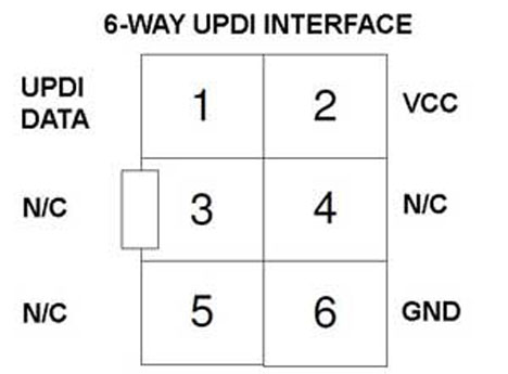
As it doesn’t have a clock, the only pin is Reset for programming data. The Reset pin can be configured to be either reset, UPDI or GPIO in fuse bytes, default for new devices is UPDI. If this is changed, a 12V pulse is needed to enter programming mode and reprogram the chip. Not all programmers support this 12V pulse so be careful when changing reset configuration or you can lock yourself out.
Although only one pin is used plus VCC and GND, Microchip recommend a 6-way 3 x 2 pin header as the programming connector.
Conclusion
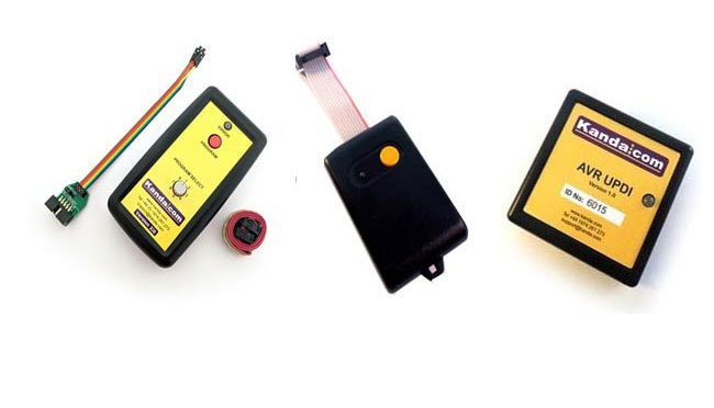
As a user, it is not usually an issue which programming method is used. Make sure your programmer supports the method you need and follow the recommended ISP circuit layout. Kanda AVR and ATxmega handheld programmers support SPI, JTAG, UPDI, TPI and PDI but the standard AVR unit only supports SPI, JTAG and TPI. See AVR and ATxmega Handheld Programmer for AVR UPDI and ATxmega PDI support.