AVR microcontrollers were first introduced almost 30 years ago and since then there have been a few changes, especially since Microchip absorbed Atmel. The AVR was one of the first microcontrollers to have onboard flash memory that could be electrically erased and reprogrammed and this enabled the introduction of In System Programming or ISP.
Read more: All You Need to Know About AVR ISP, UPDI, JTAG, PDI and TPI.History of AVR Programming Methods
The first programming method is commonly known as ISP and is a 3-wire SPI protocol. Larger chips (40-pins or more) started to have a JTAG interface for debugging and this was adopted as a second programming method.
These were the sole programming methods until the ATxmega family came along. These introduced a combined debug and program method called PDI, which is a 2-wire interface.
As this combined debug and programming interface made for easier on-chip debug and 2 wire programming, a version of it was introduced for some standard AVR ATtiny microcontrollers, called Tiny Programming Interface or TPI.
Pretty quickly, TPI was replaced by UPDI, which is a single wire debug and programming method. All AVR chips now use UPDI but it has gone through several changes and not all UPDI interfaces are the same!
ISP Interface
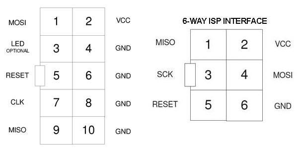
The first AVR In System Programming method is commonly known as ISP but is actually Serial Programming Interface, as it uses SPI protocol. This is a 3-wire synchronous protocol with separate clock, data in and data out lines, called SCK, MISO and MOSI.
For programming, the programmer is always the master and target AVR is always the slave, so MISO (Master In Slave Out) is input to programmer and MOSI (Master Out Slave In) is output from programmer.
Originally ATmel defined a 10-way header with lots of ground lines because they were worried about noise – don’t forget this was a very early ISP – but later recommended a smaller 6-way version. These are shown here.
Reset line needs a capacitor and resistor (typically 100nF and 10K) and you should avoid too much load on MISO, MOSI and SCK. Reset needs connecting so that programmer can enable ISP. ISP speed is dependent on target clock – maximum speed is quarter of clock and new chips have 1MHz Internal RC set so program more slowly.
VCC and GND need to be connected to ISP header to give programmer a voltage level or to enable programmers like Kanda Handheld to power target. ISP speeds needs to be slower with lower voltages.
Apart from early devices , most AVR microcontrollers with less than 40 pins also have a DebugWire Interface for on-chip debugging. This is controlled by DWEN fuse, which must be disabled before ISP can be used. DWEN is off on new devices and Microchip Studio will reset DWEN when it exits debug mode.
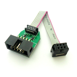
Most ISP interfaces are 2.54mm or 0.1 inch pitch but 2mm and 1.27mm (0.05 inch) can be used. Kanda have a range of different pitch adapters.
Kanda Programming AdaptersJTAG Interface
Older AVR devices with 40-pins or more usually have a JTAG interface for debugging or to use JTAG bus and this can also be act as programming interface to save on pin usage and share the same connector.
JTAG is basically a 4-wire protocol with clock TCK, data in and out TDI and TDO and control line TMS. AVR Reset pin should also be connected to NRST pin (TRST pin or tap reset does not need to be connected for programming).
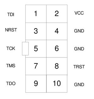
JTAG programmer speed is independent of target clock but JTAGEN fuse should always be set or JTAG interface is disabled. New chips have JTAG enabled by default. If this fuse is cleared, ISP needs to be used to reprogram it before JTAG programming can be used.
PDI Interface
The combined Programming and Debug Interface was introduced on ATxmega devices and all of these chips use PDI. This is a 2-wire protocol with PDI_CLK and PDI_DATA lines. PDI_CLK is also the Reset pin on the ATxmega chip and PDI_DATA is a dedicated pin so circuit is very simple.
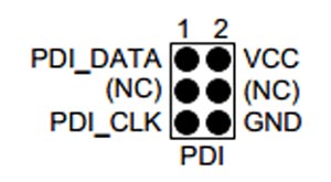
PDI interface is a synchronous serial port (USART) and programmer controls this. As PDI_Data is a dedicated pin with a built-in internal resistor, there are no fuses to worry about and PDI is always enabled. As well as connecting PDI_CLK (to Reset) and PDI_DATA pin, VCC and GND must be connected to header.
Most ATxmega chips also have a JTAG interface that can also be used for programming (if JTAGEN fuse is set) but this programming method is much slower than PDI. Typical PDI BAUD Rate is 230400 but needs to be slower at lower voltages.
TPI Interface
After the success of ATxmega PDI, Atmel decided to use it on new standard AVR ATtiny chips but called it Tiny Programming Interface or TPI. The debug equivalent is TDI or Tiny Debug Interface, which uses same pins.
TPI is also a synchronous serial port (USART). Unlike PDI, TPI uses 3 wires – TPI_CLK, TPI_DATA and AVR Reset pin. VCC and GND must also be connected. Typical speeds are the same as PDI, 230400.
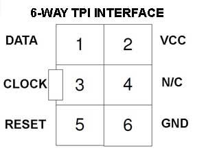
These ATtiny devices do not have dedicated programming pins and pins on PORTB are used – Data PB0, CLK PB1 and Reset PB3. Any circuit load on these pins should be isolated with suitable resistors.
Reset pin can be configured as GPIO by setting RSTDISBL fuse. If this fuse is set, TPI can only be re-enabled by applying a 12V pulse to Reset pin. Kanda handheld programmers can do this if 12V pulse is selected.
Only a limited number of ATtiny devices use TPI, older ones use ISP and later ones moved to UPDI. Here is the list:
ATtiny10, ATtiny102, ATtiny104, ATtiny20, ATtiny4, ATtiny40, ATtiny5, ATtiny9
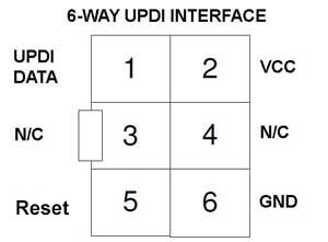
UPDI Interface
The newest interface is UPDI and appears on ATtiny, ATmega and all AVR series chips. UPDI is a 1-wire protocol and has speeds above 1Mbps, so is reasonably fast. VCC and GND must be connected and it is better to allow programmer to power target as this makes recovery from errors better. Do not put any circuitry on UPDI pin as it has enough to do with a 1-wire protocol!
There are differences between UPDI on ATtiny, ATmega and AVR as the protocol has improved.
ATtiny UPDI Interface
ATtiny microcontrollers were the first UPDI devices and they have UPDI_DATA, RESET and GPIO functions all on a single pin, so ignore Reset in above diagram for these.
UPDI function is set by default and can be changed by altering RSTPINCFG fuse. If this fuse is not set to UPDI, a 12V pulse is required on UPDI/RESET pin to re-enter UPDI mode. Kanda supply an adapter to do this.
ATmega and AVR UPDI Interface
ATmega devices with UPDI have a dedicated UPDI pin that is separate from Reset pin. Reset can be configured by RSTPINCFG fuse to be GPIO but UPDI pin can’t be changed, so it is always possible to enter UPDI.
AVRxx family shows some differences. AVR DA and AVR DB series are like ATmega, with a dedicated UPDI pin that can’t be reconfigured. Although Reset can be changed to GPIO, this does not affect UPDI entry.
AVRxxDD and AVRxxEA UPDI
AVR DD and AVR EA series, possibly because they are smaller, have both a RSTPINCFG fuse, to change Reset to GPIO, and an UPDIPINCFG fuse to reconfigure UPDI pin as GPIO. If this fuse is set, UPDI can only be re-enabled by applying 12V to Reset pin (NOT UPDI pin). Kanda programmers can do this without an adapter.
Conclusion
From a users point of view, the main things to worry about are target pin-out required for each interface, what fuses should be approached with caution and how to avoid loading programming lines, which will prevent device from programming.
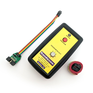
Kanda Handheld Programmers
Kanda Handheld AVR Programmers support all programming interfaces – ISP, JTAG, TPI, PDI (ATxmega) and UPDI. They are available as single and 8 program versions.
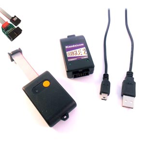
Kanda Keyfob Programmer
Kanda AVR Keyfob Programmers support ISP and UPDI programming interfaces.
Kanda AVR UPDI Programmer
New Kanda AVR UPDI programmer supports all ISP AVR microcontrollers, including AT90S, JTAG programmer and all AVR UPDI devices, including ATtiny, ATmega and all new AVRxx series.