
What is CAN bus? Officially, CAN is a Controller Area Network, which is a network of independent controllers communicating securely. It was first developed by Bosch and Intel in 1990 and has been amended since. The International Standards Organisation (ISO) has further defined CAN using their OSI model.
Open System Interconnect or OSI is a standard model for communication architecture, consisting of 7 layers
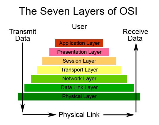
CAN Bus is defined in ISO 11898 but this only covers the bottom two layers. Other standards such as CAN Open and SAE J1939 are extensions to the CAN standard that define high level layers, but specific (expensive) software is needed to deal with these protocols.
Physical Hardware
On the physical layer, CAN consists of two dedicated wires for communication. These wires are called CAN high and CAN low. When the CAN bus is in idle mode, both of these lines carry 2.5V but when data bits are being transmitted, the CAN high line goes to 3.75V and the CAN low drops to 1.25V. This generates a 2.5V voltage differential between the two lines, so the CAN bus is NOT sensitive to inductive spikes, electrical fields or other noise. This makes CAN bus very resilient in an electrically noisy environment, like a vehicle. Using twisted-pairs makes it even more robust. The lines must be terminated at each end with a 120R resistor.
Power can be supplied through CAN bus wires, or a power supply for the CAN bus modules can be arranged separately. The power supply wiring can be either totally separate from the CAN bus lines (using suitable gauge wiring for each module) resulting in two 2-wire cables being utilized for the network, or it can be integrated into the same cable as the CAN bus lines giving a single 4-wire cable.
This hardware interface is best achieved using a CAN Transceiver chip that deals with all the necessary electrical interfacing.
Data Transmission
The Data Link Layer allows all modules to transmit and receive data on the bus, ie no master. Each module is given a unique CAN ID, either 11-bit (CAN 2.0 A) or 29-bits (CAN 2.0 B), that it uses when it sends messages and it responds to. All modules will also respond to a broadcast message.
The maximum data throughput defined by the standard is 1Mbit/s and common rates are 125Kbits/sec for Can Open and 250Kbits/sec for J1939. Communication distances also varies with the bit rate. 1Mbit/sec has a maximum distance of 40 metres, 250Kbit/sec up to 250 metres and 10 Kbits/sec up to 1Km.
CAN Frame
CAN communication relies on frames, whose format is defined by the standard. A frame can be a data frame, an error frame or remote frames. Each frame includes start and stop bits, CAN ID or address, data, check bits and frame type.
Each CAN node will only respond to a message that has its ID or a broadcast ID. and other frames are ignored.
- Data Frame – used to send data
- Remote Frame – used to request data
- Error Frame – used to report error condition.
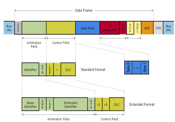
The ID field has two functions, one to determine the node that should get the message and secondly to determine the message priority by arbitration. A zero in any bit position will give the message priority, so 0000… will take priority over 0001… for example. So, the lower the ID, the higher the priority. Each node should have a unique ID otherwise arbitration will fail.
The frame also contains check sum (CRC), ACK and other bits that we do not need to worry about.
CAN Data Fields
A CAN Data frame can contain up to 8 bytes of data. The DLC (Data Length Code) contains the exact number of bytes. A remote frame does not include data and DLC is set to zero. CAN FD has different data length, see below.
CAN Bus System
CAN is used because it is extremely robust with excellent error control. Each node on a CAN Bus will have a CAN transciever that sets the electrical signals, a CAN Controller that deals with assembling and transmitting frames and a microcontroller that is used to control the node e.g. by reading a sensor, alarm signal or other function and sending the data to the CAN Controller.
All of these system elements are available indidually or as a package as some microcontrollers include a CAN Controller and some CAN controllers have a built-in CAN transceiver.
CAN Bus system design is relatively straightforward as each node is given an ID that sets its priority – the lower the ID, the higher the priority. Most CAN Controllers have both I2C and SPI interfaces to the microcontroller in the node. So, your microcontroller code just needs to initialse the controller and send raw data when required. The controller takes care of actually assembling the frame, sending the message and dealing with errors.
The CAN controllers deals with the Data Link layer and you are designing the higher application layer.
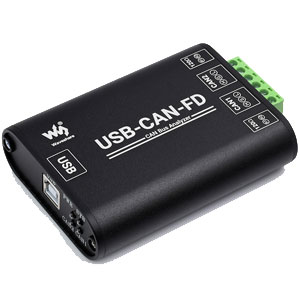
PC Interface
Most CAN systems have a node on the PC to analyse data and set up and control the system, although a standalone module could be used instead.
CANUSB is a CAN bus USB interface that supports both CAN 2.0A and CAN 2.0B (11 and 29-bit IDs) but doesn’t support CANOpen or J1939, although there is a shareware CANOpen project available. It is ideal for connecting your CAN bus to USB port on the PC for diagnostics, control and monitering. CAN232 is a product to give an RS232 to CAN bus interface.
CAN FD
CAN FD is the newest defined standard for CAN bus. It is very similar to standard CAN – same message format, ID scheme etc. but the data field of each message can be up to 64 bytes instead of 8 byte maximum of standard CAN.
The maximum speed of CAN-FD is also greater, up to 5Mbsp instead of 1Mbps. You will need a different CAN Controller for CAN FD and a different PC interface. Kanda sell an adapter for connecting PC to a CAN FD network.
Dual CAN FD Adapter
CAN Bus and OBD2
Finally, to clear up some confusion, CAN bus is not the same as OBD or OBD2 for vehicles. OBD2 actually defines a 16-bit connector that must be fitted on all new vehicles, near steering wheel. Different pins on this connector are defined for different communication protocols used by different manufacturers.
| Pin | Signal | Description |
| 2 | J1850 Bus+ | |
| 4 | CGND | GND |
| 5 | SGND | GND |
| 6 | ISO 15765 CAN High | J-2284 |
| 7 | ISO 9141-2 K-LINE | Tx/Rx |
| 10 | J1850 Bus- | |
| 14 | ISO 15765 CAN Low | J-2284 |
| 15 | ISO 9141-2 L-LINE | Tx/Rx |
| 16 | +12v | Battery power |
There are 5 different protocols defined on the OBD-II connector, including J1850 PWM used by Ford, J1850 VPW used by General Motors, ISO 9141-2 for Chryler, ISO14230 KWP2000 on some EU and Asian cars, and most important from our point of view, ISO 15765, which is CAN for vehicles. Since 2008 all new vehicles have had to support CAN, so the other protocols will die out over time.
CANUSB could be used to read CAN signals from a vehicle by connecting CAN_L, CAN_H and CAN GND to the correct pins on OBD-II connector, but without software to interpret the messages they would be pretty meaningless. So, if you want to interrogate your car, get an OBD-II scanner or scan tool, which uses PID codes defined by SAE J1979.
CANUSB – USB to CAN bus interface.
You have more useful info than the Bristih had colonies pre-WWII.
I know more about CAN bus,Described in great detail
Hello hopefully you can help. I need to know if 08 GM Can Bus system can be made to work in an 05 GM. This is a motor and transmission swap., Both are 6L and 4L80E using the 08 harness and computers. So all 08 2500HD into an 05 2500HD. Thank you.
Regards Lyle @ 250 713 4223 or lmcchesney777@gmail.com
Not a clue I’m afraid, I don’t even know what you are talking about.