
CAN BUS EXPLAINED
Part 2: Frames, Arbitration and Fault Tolerance
Introduction
In Part 1 we explored why CAN was developed, how a CAN network is structured and how differential signalling provides exceptional immunity to electrical noise.
Those physical-layer concepts explain how information travels across the network, but they do not explain what is actually being transmitted or how dozens of electronic control units can communicate simultaneously without descending into chaos.
That responsibility lies with the CAN protocol itself.
In this article we examine the structure of CAN messages, how nodes compete for access to the shared bus, the timing requirements that make reliable communication possible and the sophisticated error-handling mechanisms that have made CAN one of the world’s most dependable industrial communication protocols.
CAN Frame Overview
Every exchange of information on a CAN network is carried within a structured data packet known as a CAN frame.
Rather than transmitting raw bytes, CAN organises information into well-defined fields that allow every node on the network to identify, validate and interpret each message consistently.
Each field serves a specific purpose, from identifying the message and transporting application data to detecting transmission errors and marking the end of the frame.
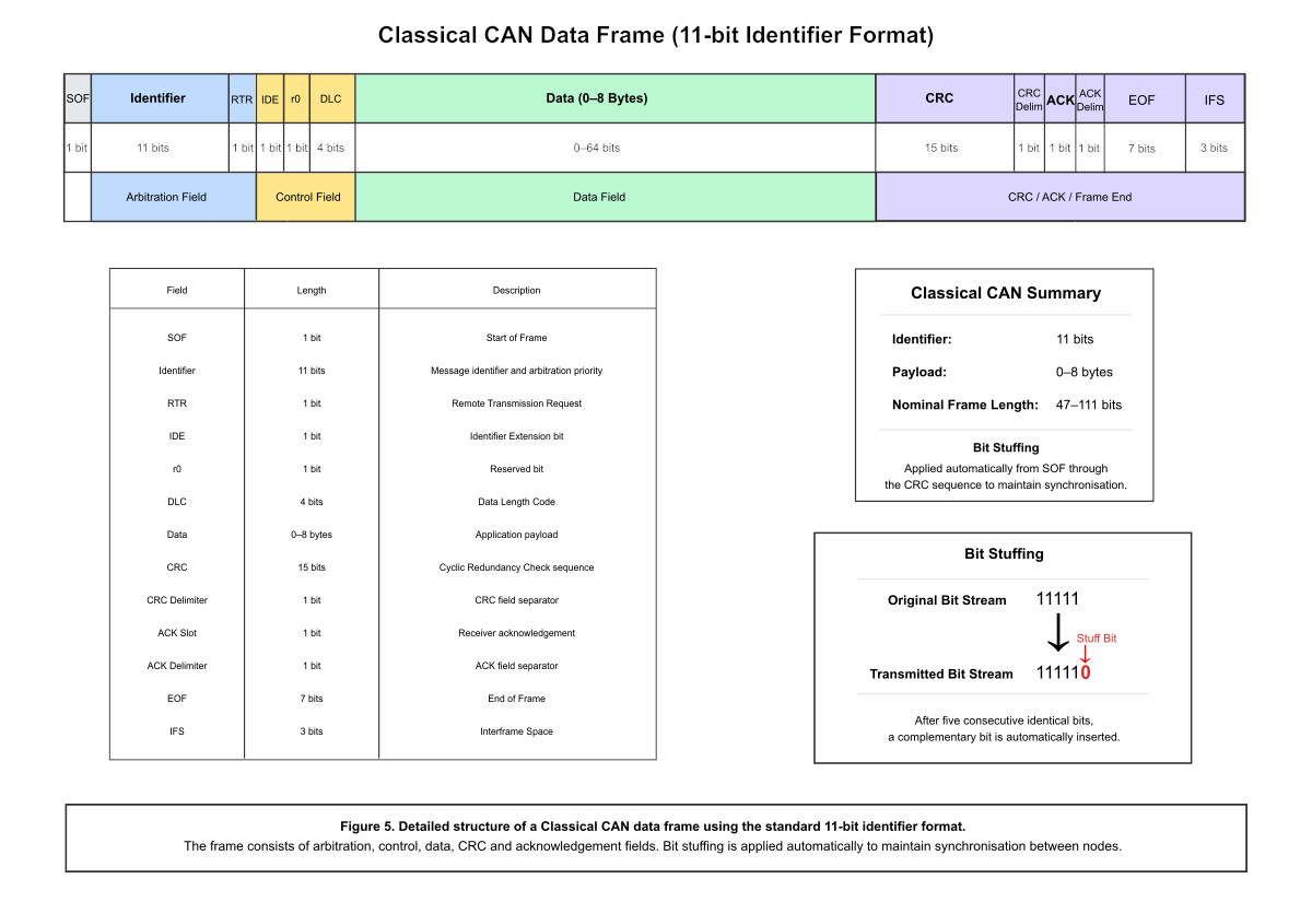
Although several frame types exist within the CAN specification, the data frame is by far the most commonly encountered and forms the basis of almost all normal network communication.
Standard and Extended Frames
CAN supports two message identifier formats.
The original specification defines an 11-bit identifier, commonly referred to as the standard frame format. As networks became increasingly complex, an extended 29-bit identifier was introduced to provide a significantly larger address space.
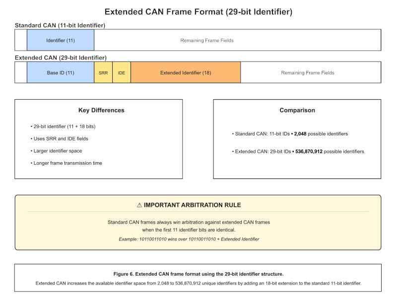
Importantly, both formats can coexist on the same physical network. The arbitration mechanism ensures that nodes using either identifier format continue to communicate reliably while maintaining deterministic bus access.
The choice between standard and extended identifiers is determined by the requirements of the higher-level protocol and the number of unique messages that must be supported by the network.
Bus Arbitration
One of the defining characteristics of CAN is that it is a multi-master protocol. Any node on the network may begin transmitting whenever the bus is idle.
Naturally, this raises an important question:
What happens if two nodes start transmitting at exactly the same time?
Rather than treating simultaneous transmissions as collisions, CAN resolves them using a process known as non-destructive bitwise arbitration.
Every transmitting node continuously monitors the bus while sending its identifier. Dominant bits always overwrite recessive bits on the physical network, allowing the highest-priority message to continue uninterrupted while lower-priority nodes automatically cease transmission.
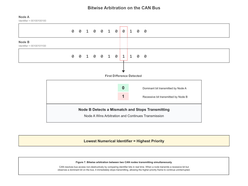
This approach provides two major advantages:
- No bandwidth is wasted by collisions.
- The highest-priority message always gains immediate access to the bus.
Because arbitration occurs during the identifier field, message identifiers represent both the identity of a message and its priority within the network.
Message Priority
Unlike many communication protocols where priority is assigned separately, CAN embeds priority directly into the message identifier.
Numerically lower identifiers contain more dominant bits near the beginning of the arbitration field and therefore have higher priority.
For example:
0x080has higher priority than0x180.0x001has higher priority than almost every other message on the network.0x7FFis the lowest-priority standard identifier.
Careful allocation of identifiers is therefore an important part of CAN network design. Safety-critical messages such as braking or steering are typically assigned higher priorities than diagnostic or informational traffic.
Bit Timing
Reliable communication depends not only on message format but also on every node interpreting each transmitted bit at precisely the correct instant.
To achieve this, each CAN bit is divided into a number of time segments that allow receivers to synchronise with the transmitter while compensating for oscillator tolerances and propagation delays.
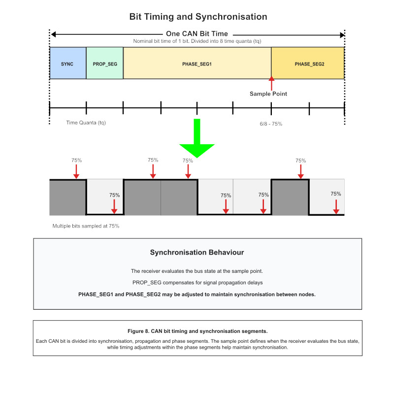
A typical bit consists of:
- Synchronization Segment (
Sync_Seg) - Propagation Segment (
Prop_Seg) - Phase Buffer Segment 1 (
Phase_Seg1) - Phase Buffer Segment 2 (
Phase_Seg2)
Together these segments determine the location of the sampling point, which is the instant at which receivers determine whether the transmitted bit is dominant or recessive.
Selecting appropriate bit timing parameters is essential for achieving reliable communication, particularly on long networks or at higher data rates.
Bit Stuffing
CAN uses a technique known as bit stuffing to maintain clock synchronisation between transmitting and receiving nodes.
Whenever five consecutive bits of the same polarity are transmitted, the controller automatically inserts a complementary stuff bit into the bit stream.
The receiving controller removes these bits automatically before reconstructing the original message, making the process completely transparent to the application.
In addition to maintaining synchronisation, incorrect bit stuffing also provides another mechanism for detecting transmission errors.
Error Detection
One of the primary reasons for CAN’s widespread adoption is its exceptional reliability. Rather than relying on a single error-checking mechanism, the protocol employs multiple independent techniques to detect communication faults before corrupted data can propagate through the network.
During every transmission, both the transmitting node and all receiving nodes continuously monitor the integrity of the message.
CAN implements several complementary error detection mechanisms, including:
- Cyclic Redundancy Check (CRC)
- Frame format checking
- Bit monitoring
- Bit stuffing verification
- Acknowledgement monitoring
If any of these mechanisms detects an inconsistency, the current transmission is immediately aborted and an error frame is generated to notify every node on the network.
The original message is then retransmitted automatically, ensuring reliable delivery without intervention from the application software.
Fault Confinement
Detecting communication errors is only part of the solution. CAN must also prevent faulty nodes from disrupting an otherwise healthy network.
To achieve this, every controller continuously evaluates its own behaviour using two internal error counters:
- Transmit Error Counter (TEC)
- Receive Error Counter (REC)
These counters increase when communication errors occur and decrease again following successful transmissions or receptions.
Depending on their values, the controller automatically transitions through three operating states.
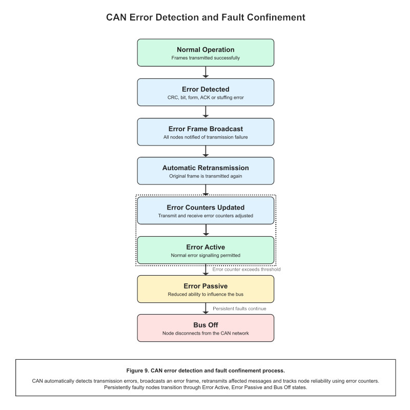
- Error Active — Normal operation with full participation on the network.
- Error Passive — The node remains operational but has a reduced influence on bus communication.
- Bus Off — The controller disconnects itself from the network to prevent further disruption.
This automatic fault confinement mechanism ensures that a malfunctioning controller cannot continuously corrupt communication for every other node connected to the bus.
Once the underlying fault has been resolved, recovery procedures defined by the CAN specification allow normal operation to resume safely.
Why CAN Is So Reliable
The combination of deterministic arbitration, differential signalling and comprehensive error handling gives CAN a level of robustness that few communication protocols can match.
Rather than depending on any single protective feature, CAN layers multiple mechanisms together:
- Differential signalling rejects electrical noise.
- Non-destructive arbitration eliminates message collisions.
- CRC verification detects corrupted frames.
- Bit monitoring validates transmitted data.
- Automatic retransmission recovers from transient faults.
- Fault confinement isolates malfunctioning nodes.
These mechanisms operate continuously and transparently, allowing networks to maintain reliable communication even in electrically noisy or safety-critical environments.
Key Takeaways
In this article we explored the protocol layer that makes CAN such an effective communication system.
We examined how CAN frames are structured, how deterministic arbitration allows multiple nodes to share a common bus, how accurate bit timing ensures reliable sampling and how multiple layers of error detection and fault confinement combine to produce one of the most dependable communication protocols ever developed.
These concepts form the foundation for understanding more advanced developments such as CAN FD and modern diagnostic techniques.
In Part 3, we build on these foundations by exploring CAN FD, practical network design considerations and the hardware and software tools required to analyse and debug real CAN systems.