
CAN BUS EXPLAINED
Part 1: Origins, Architecture and Differential Signalling
Introduction
Few communication technologies have had as much impact on embedded systems as the Controller Area Network, better known as CAN bus.
Originally developed for automotive applications in the 1980s, CAN has become one of the most successful industrial communication protocols ever created. Today it can be found in passenger vehicles, commercial transportation, industrial automation systems, medical equipment, agricultural machinery, aerospace platforms and countless embedded products.
Its success stems from an elegant combination of simplicity, robustness and deterministic behaviour. CAN allows multiple electronic control units (ECUs) to communicate over a shared two-wire network without requiring a central controller, while maintaining excellent fault tolerance and noise immunity.
For embedded engineers, understanding CAN is essential. Whether designing automotive electronics, industrial control systems, robotics platforms or diagnostic equipment, CAN remains one of the most widely deployed communication technologies in modern embedded design.
This three-part series explores CAN from the physical layer through to advanced protocol operation. In this first article, we examine the origins of CAN, its network architecture and the differential signalling techniques that make reliable communication possible in electrically noisy environments.
Why CAN Was Needed
Before CAN was introduced, vehicle electronics relied heavily on dedicated point-to-point wiring.
Each electronic subsystem required its own collection of signal wires connecting sensors, switches, actuators and controllers. As vehicles became more sophisticated, wiring harnesses grew rapidly in size and complexity.
Problems quickly emerged:
- Increasing vehicle weight
- Higher manufacturing costs
- Reduced reliability
- Difficult fault diagnosis
- Limited scalability
Adding a new feature often required additional wiring throughout the vehicle, creating engineering and manufacturing challenges.
A better solution was needed.
Rather than connecting every module directly to every other module, engineers began exploring shared communication networks where multiple devices could exchange information over a common bus.
This led to the development of CAN.
The Birth of CAN
CAN was originally developed by the German company Robert Bosch GmbH during the early 1980s.
The goal was ambitious:
- Reduce vehicle wiring complexity
- Improve reliability
- Support distributed control systems
- Enable real-time communication
Unlike traditional master-slave protocols, CAN was designed as a multi-master network. Any node could initiate communication whenever the bus became available.
The protocol was formally introduced in 1986 and rapidly gained acceptance throughout the automotive industry.
Its combination of robustness, simplicity and deterministic arbitration made it ideal for safety-critical systems.
Today, CAN forms the foundation of numerous higher-level standards, including:
- CAN in Automation protocols
- CANopen
- DeviceNet
- J1939
- Automotive diagnostic networks
Evolution of Vehicle Communication Networks
As vehicle electronics evolved, communication architectures progressed through several distinct generations.
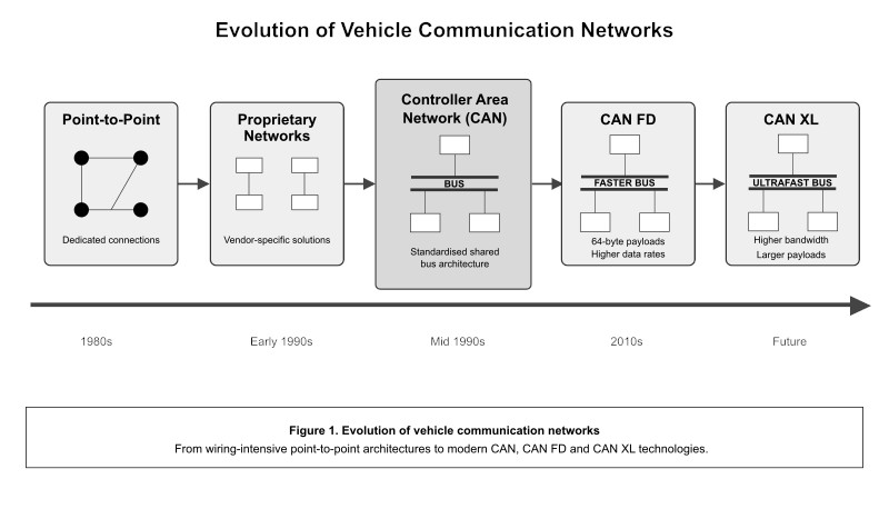
Early systems relied entirely on dedicated point-to-point wiring.
As electronic content increased, proprietary network solutions began to appear. These reduced wiring but often lacked interoperability between manufacturers.
CAN provided a standardised solution that offered:
- Reduced wiring complexity
- Improved reliability
- Deterministic communication
- Multi-master operation
- Excellent scalability
Subsequent developments such as CAN FD and CAN XL further extended network bandwidth and capability while maintaining compatibility with the fundamental CAN architecture.
CAN Network Fundamentals
At its core, a CAN network consists of multiple nodes connected to a shared communication medium.
Each node may represent:
- An engine controller
- A transmission controller
- A body control module
- A sensor subsystem
- An industrial controller
- A diagnostic tool
CAN Node Architecture
Every CAN network consists of intelligent nodes connected to a common communication bus.
Although implementations vary, most CAN nodes share the same fundamental architecture.
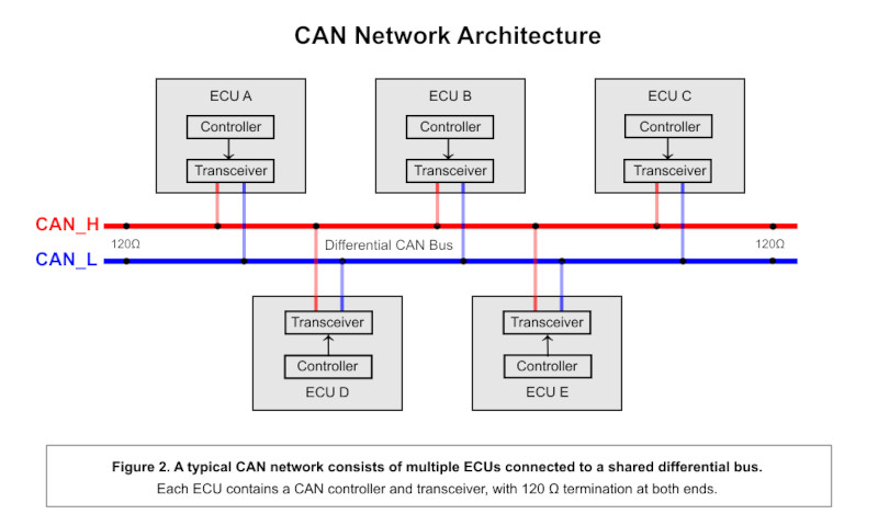
A typical node contains:
- A host microcontroller responsible for application software.
- A CAN controller that implements the communication protocol.
- A CAN transceiver that converts logic-level signals into the differential voltages placed onto the physical bus.
Together these components allow each node to send, receive and interpret messages while sharing a common communication medium with every other node on the network.
Because every node connects to the same bus, additional devices can often be integrated without major changes to the overall network architecture.
Inside a CAN Node
Looking more closely at an individual node reveals how data flows from application software onto the physical network.
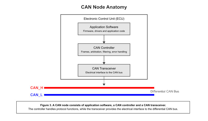
The host processor generates application data that must be transmitted across the network.
This information passes to the CAN controller, which performs protocol functions including:
- Frame generation
- Arbitration
- Error detection
- Message filtering
- CRC generation and checking
The CAN transceiver then converts the controller’s digital transmit signal into the differential voltages required by the physical bus.
Incoming differential signals follow the reverse path, allowing received frames to be processed by the application software.
Differential Signalling
One of CAN’s greatest strengths is its use of differential signalling.
Instead of transmitting information on a single wire referenced to ground, CAN uses two complementary signal lines:
CAN_HCAN_L
Information is represented by the voltage difference between these two conductors rather than their absolute voltage levels.
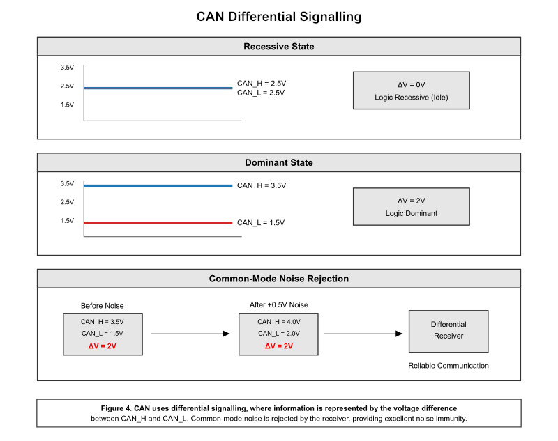
During a dominant bit, the CAN transceiver actively drives the bus so that CAN_H rises while CAN_L falls, creating a measurable differential voltage.
During a recessive bit, both lines return to approximately the same voltage, resulting in little or no differential voltage between them.
Because external electromagnetic interference generally affects both wires equally, the differential voltage remains largely unchanged. The receiver therefore rejects most common-mode noise automatically.
This technique provides exceptional immunity to electrical interference, making CAN highly reliable in demanding environments such as vehicles, factories and heavy industrial equipment.
Key Advantages of CAN
The combination of multi-master communication, message-based networking and differential signalling gives CAN several significant advantages over many traditional communication systems.
- Reduced wiring complexity.
- Excellent electrical noise immunity.
- Deterministic message prioritisation.
- Automatic error detection and recovery.
- High reliability in harsh operating environments.
- Scalable network architecture.
- Wide industry adoption and mature tooling.
These characteristics explain why CAN has remained one of the world’s most successful embedded communication protocols for more than four decades.
Key Takeaways
In this article, we explored the origins of Controller Area Networks, the problems they were designed to solve and the physical architecture that underpins every CAN system.
We introduced the concepts of shared-bus communication, CAN node architecture and differential signalling, demonstrating how these foundations provide the robustness and reliability for which CAN is renowned.
In Part 2, we move beyond the physical layer to examine how CAN messages are structured, how arbitration works and how the protocol achieves deterministic communication while maintaining exceptional fault tolerance.