Microchip PIC Programmer ICSP Circuit Requirements
Microchip do not recommend any particular circuit for ICSP programming. There are diagrams for different
tools, such as Pro Mate and PICKit2 with similar circuitry but slight variations. In some schematics, their suggested
resistor values are too small, in our opinion, and can cause problems with programmers, even Microchip ones.
Popular Products
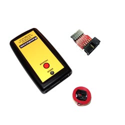
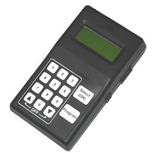
PIC Handheld Programmer
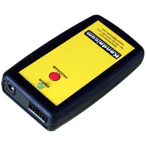
Simple to load and use, standalone battery powered PIC Handheld Programmer
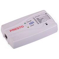
Low Cost PIC Kit
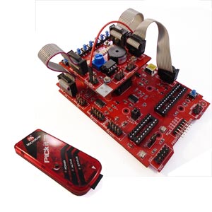
Best value PIC board on the market, with PICKit3 debugger and programmer
Microchip PIC Programmer ICSP Circuit
Kanda have developed a recommended In System Programming circuit that will work effectively with our
PIC programmer range,
and other PIC programmers. This circuit is shown
in the diagram below. Please read the notes that describe the circuit and explain the effect of extra components
such as capacitors.
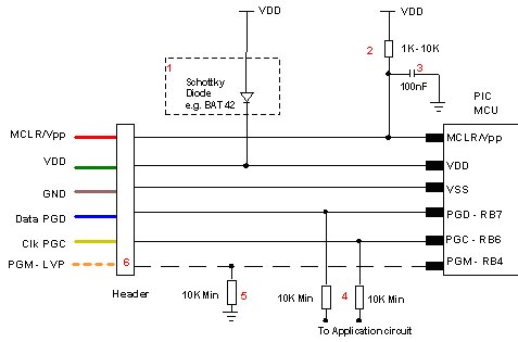
Notes on PIC ICSP Circuit
- Kanda programmers are designed to provide 3.3V or 5V to the target circuit, but some other ICSP programmers always supply 5V.
If your circuit operates at a lower voltage than the programmer, then the diode shown on VDD should be fitted to protect the rest
of the circuit. A series resistor may be acceptable instead of the diode in some cases.
The maximum current that the programmer can supply is often limited, so you should fit the diode on
VDD if the programmer over-current circuit trips.
- MCLR/VPP pin needs a resistor to VDD. A minimum of 1K should work but 10K is better. PIC16F
devices with only VDD first ICSP entry (PIC16F8x/87x/7x/7x7) should be fitted with a 4K7 resistor as a
minimum to reduce the possibility of code running before VPP rises.
Supervisory circuits or push buttons on MCLR should be isolated from the VPP voltage, by placing them
on the VDD side of the resistor or by fitting a Schottky diode on this line as per note 1.
- The 100nF capacitor shown on MCLR/VPP pin is optional for HVP but we do recommend that a capacitor
is fitted to avoid glitches on MCLR. 100nF is the maximum value, and we recommend something
smaller. Larger capacitors may prevent the PIC from entering HVP mode. Do not fit for LVP mode.
- If possible, Clock and Data lines should be dedicated to ICSP but where this is not possible,
the application circuit should be isolated from the data and clock lines with series resistors, above 10K.
This is especially important if either of these lines forces the pin as an input or output. In exceptional
cases, series resistors may not be sufficient and a 4053 multiplexer or similar circuit should be used.
Capacitors on these programming lines should be avoided if at all possible. If they are needed, for noise immunity
for example, then the maximum capacitance that all programmers can handle is 1nF, although some are better.
- If LVP mode is used, this resistor must be fitted.
- The PGM line is only needed for Low Voltage Programming - LVP mode.
- PIC18F J parts need a decoupling capacitor between VccCore pin and Ground, typically 100nF.
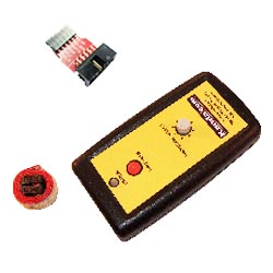
Kanda ICSP PIC Programmers
Kanda Handheld PIC Programmers will provide 3.3V or 5V VDD to target PIC microcontroller circuits. The target
circuit can be powered or unpowered. This can be user selected for most PIC microcontrollers but it is
fixed to 3.3V for J type PIC microcontrollers and LF parts that can be damaged by 5V.
The high Voltage programming voltage (VPP) is set to 12V for most PIC devices but is automatically set to 9V for
PIC18F K type and newest PIC16F PIC microcontrollers.
Popular PIC Products